Oversampling method and its application to x-ray diffraction
- A novel x-ray microscopy in nano/atomic resolution -
[Principle]
An x-ray diffraction intensity is proportional to the square amplitude
of the Fourier transform of an object image (an electron number density)
in the kinematical theory. If the phase of the Fourier transform is also
measured, the object image can be reconstructed by back Fourier transformation.
However the phase is not directly obtained in x-ray diffraction measurement.
Therefore the half of necessary information for image reconstruction is
missing. The problem is known as the phase problem.
The oversampling method is a solution to the phase problem. In
the method a zero density region around the sample object is assumed.
If the zero density region is larger than the sample region, more than
half of total information is known in real space. Therefore it is in principle
possible to use the zero density information to make up for the missing
phase information.
In the oversampling method the following iterative procedure
is taken:
..... → Image of n-th iteration →
Fourier transformation →
Set Fourier amplitudes to known (measured) values →
Back Fourier transformation →
Set the density in the zero density region and at negative
density pixels gradually to zero →
Image of (n+1)-th iteration → .....
[Simulation 1]
We consider a 2-dimensional sample image and a zero density region
around it in discretized real space (Fig. 1), and its Fourier transform
in the first Brillouin zone of discretized reciprocal space (Fig. 2).
Fig. 1 Sample image with zero
density region around it
|
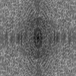
Fig 2. Oversampled Fourier
transform (a simulated diffraction pattern)
|
 (256 x 256 pixels)
|
 log scale (256 x 256 pixels)
 |
The diffraction pattern is oversampled due to the zero density region
in real space. It means that the diffraction pattern is sampled finer
than the frequency determined by the sample image size.
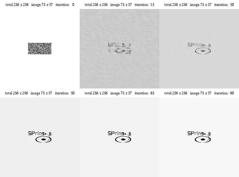
In the simulation a random image in the sample region was taken
as the initial image. After 80 iterations the original image was almost
perfectly reconstructed. Total computation time was 2.83 sec on an Athlon
900 MHz PC.
Fig 3. Iterative improvement of image

The resultant reconstructed image may be translationally shifted or
centro-inverted depending on a given initial image, because they give the
same diffraction amplitude.
[Simulation 2]
An example with a lager and more complex sample
image
Y. Nishino
 (256 x 256 pixels)
 log scale (256 x 256 pixels)
 (256 x 256 pixels)
 log scale (256 x 256 pixels)